
Properly performing Point of Care Ultrasound involves understanding the ultrasound knobs, machine, and equipment. But you may have issues finding a resource that allows you to easily learn how to understand and use the ultrasound machine.
In this post, I will go over the most common Ultrasound Knobology (knobs/buttons), Probes, Modes, Movements, Orientations, and Planes you will need to properly scan. By learning these ultrasound basics, you will be able to have the fundamentals on how to use any ultrasound machine you may encounter!
This post mainly goes over ultrasound machine settings, probes, buttons, and functions. I also created another post on a simple way of learning Ultrasound Physics and Artifacts you can access by clicking HERE.
Table of Contents
Choosing the Right Ultrasound Probe (Transducer)
Choosing the Right Ultrasound Probe based on Application
The single most important factor that will determine if you can get proper ultrasound images is choosing the correct ultrasound probe or transducer. Like with anything else you do, the right tool will be needed for the right situations. For example, if you used a linear probe, that has great resolution but minimal depth, you will not be able to visualize much if any of the heart.
So before you start scanning, always ask yourself these questions to help pick your ultrasound probe:
- What application am I using the ultrasound machine for?
- How deep are the structures I’m trying to visualize?
- How big or small of a footprint do I need?
- Does it involve a procedure?
- Does it involve a cavity (pelvic, peritonsillar abscess)
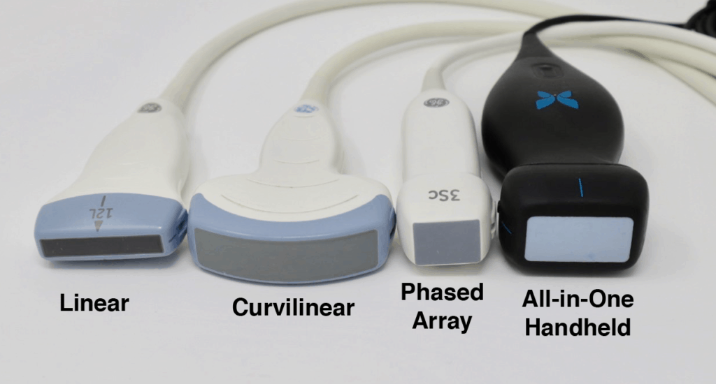
In this post we will go over the 4 most common Point of Care Ultrasound probes you will encounter (linear, curvilinear, phased array, and endocavitary probes). The table below lists when you should think about using each type of ultrasound probe.
| Ultrasound Probe | Frequency | Applications |
|---|---|---|
| Linear | 5-15 MHz | Soft tissue, Musculoskeletal, Pediatric, Ocular, Trachea, Thyroid, Thoracic, Most Procedures, DVT, Appendicitis, Testicular |
| Curvilinear | 2-5 MHz | General Abdominal (Gallbladder, Liver, etc), eFAST, renal, aorta, IVC, Bladder, Bowel, OB/Gyn |
| Phased Array/Sector | 1-5 MHz | Cardiac, Abdominal, eFAST, Renal, Bladder, Bowel, IVC |
| Endocavitary | 8-13 MHz | OB/Gyn, Peritonsillar Abscess |
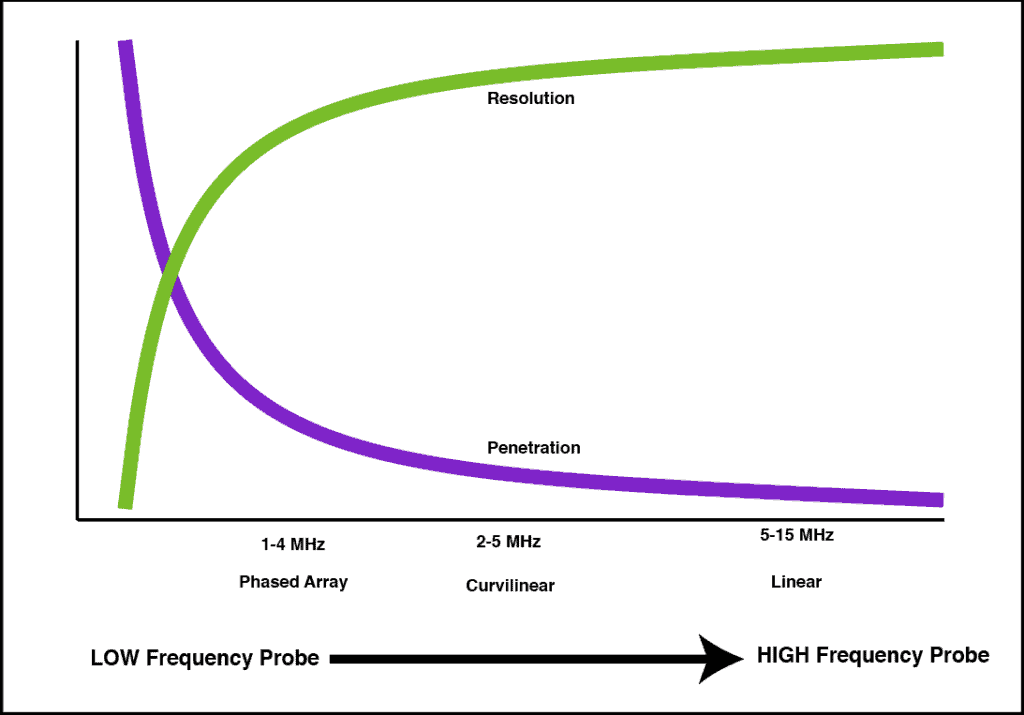
Each ultrasound probe will have it’s pros and cons. Usually, the most important factors to decide on are resolution, penetration, and footprint size. Here is a figure showing how penetration and resolution are affected with respect to the frequency of the transducer.
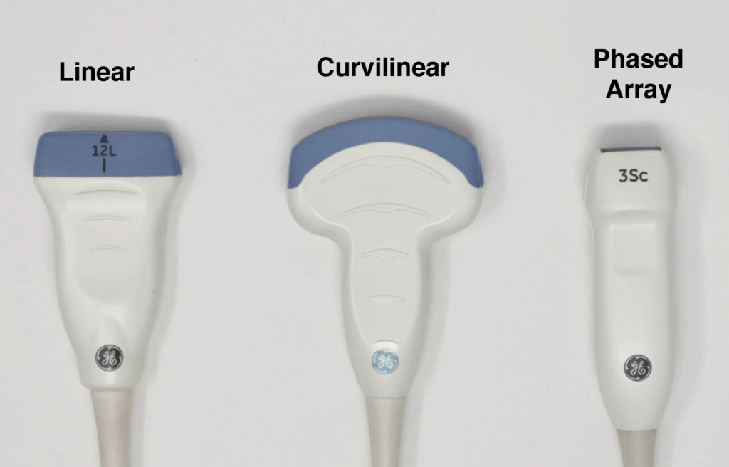
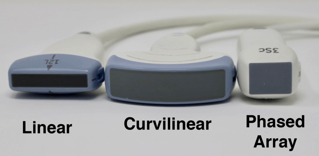
The Ultrasound Probe “Footprint” refers to the area on the probe that comes in contact with the patient’s skin in order to produce an ultrasound image. It is located at the very tip of the probe and is usually has a soft “rubbery” feel. Depending on the application you may want a smaller or larger footprint. Regarding footprint width from largest to smallest it goes: Curvilinear > Linear > Phased Array.
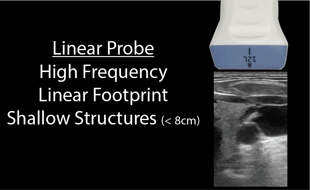
The images below demonstrate the relative sizes and footprints of the 3 most commonly used ultrasound probes (Linear, Curvilinear, and Phased Array):
Linear Ultrasound Probe
The linear ultrasound probe is a high-frequency transducer (5-15 MHz) that will give you the best resolution out of all of the probes but is only able to see superficial structures. A general rule of thumb is that if you are going to ultrasound anything less than about 8cm, then use the linear probe. Anything above 8cm you won’t be able to see much.
The linear probe will give you a rectangular field of view that corresponds with its linear footprint:
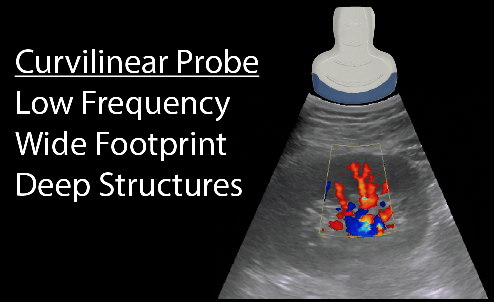
Curvilinear Ultrasound Probe
The curvilinear ultrasound probe has a frequency range of 2-5MHz. It is considered a low-frequency probe and has a large/wide footprint, allowing for better lateral resolution (compared to the phased array probe). The curvilinear ultrasound probe is often used for abdominal and pelvic ultrasound exams. However, it can also be used for cardiac and thoracic ultrasound exams but is limited by the large footprint and difficulty with scanning between rib spaces.
Here is what the Curvilinear probe looks like and how an ultrasound image will appear on the screen. Notice the curved nature of the ultrasound image.
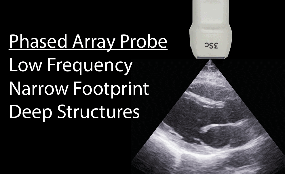
Phased Array (Sector) Ultrasound Probe
The phased array (or sector array) transducer is commonly branded as the “cardiac probe” and has a frequency range from 1-5MHz. It has a similar frequency range as the curvilinear probe but has a smaller and flat footprint.
The advantage of this probe is that piezoelectric crystals are layered and packed in the center of the probe making it easier to get in-between small spaces such as the ribs (notice the extremely small pinpoint footprint on the ultrasound image below).
It is the ideal probe for cardiac scanning however it can perform all of the applications the curvilinear probe can as well (with less lateral resolution).
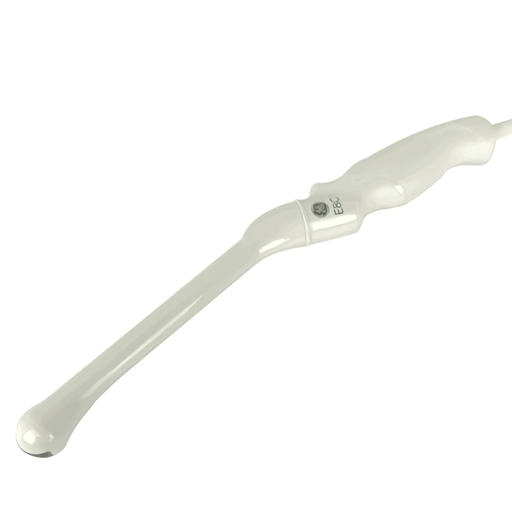
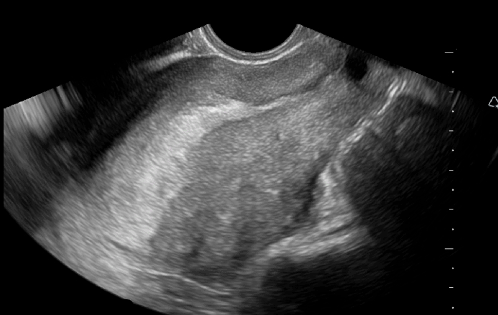
Endocavitary Ultrasound Probe
The endocavitary probe has a curvilinear footprint with a wide view but has a much higher frequency (8-13 MHz) than a curvilinear ultrasound probe. The image resolution of the endocavitary probe is exceptional, but like the linear probe, it must be adjacent to the structure of interest since it has such a high frequency/resolution, but poor penetration.
The most common POCUS applications for the endocavitary ultrasound probe are for intraoral (peritonsillar abscess) and transvaginal applications (early pregnancy, ovarian torsion, ovarian cyst, fibroids, ectopic pregnancy, etc). Make sure to always place a sterile endocavitary probe cover (condom or glove) prior to scanning.
The All-in One Handheld Ultrasound Probes:
The ultrasound probes just described are for the traditional cart-based systems.
However, there are now handheld devices that connect to your smartphone and can simulate multiple probe types with just a click of the button. The Butterfly Ultrasound Device is an example of this (see below). From my experience, the footprint is slightly larger than the phased array and the weight of the probe is about 2-3 times more than a typical phased array. This increased weight is accounted for by the processor and the battery.
Like this Post?
Sign Up For POCUS 101 Updates!

Ultrasound Probe Movements and Manipulation
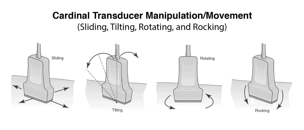
Handling the ultrasound probe and proper movement is essential to obtaining optimal ultrasound images. There are traditionally 4 basic movements that are performed when scanning with ultrasound they are Slide, Rock, Tilt(Fan), Rotate. Another technique that could be considered a “5th” cardinal movement is Compression.
Here is a quick 45 second video we made for you that shows all of the essential ultrasound movements:
It is very important that you master each of these ultrasound transducer manipulation/movement techniques. Most experienced sonographers think what manipulation or combination of movements will give them the desired image. In their minds, they know how each transducer manipulation should change their image. With deliberate practice, you will be able to do this too!
POCUS 101 Tip: For learners, really trying to improve, I always suggest that when you see a suboptimal image, think to yourself what is the next best transducer manipulation you can perform to get an optimal image. Too often, learners try a random combination of transducer movements without thinking first what the image should look like prior to manipulating the transducer.
SLIDING The Ultrasound Probe
Sliding involves moving the entire probe in a specific direction to find a better imaging window. This is usually used to find the best window, move to different areas of the body, or to follow a specific structure (such as a vessel).
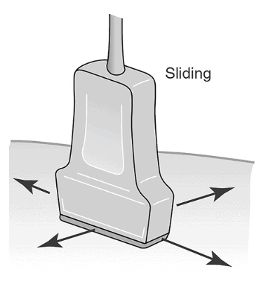
(Editors Note: There is some more recent literature that suggests that the term “sliding” should indicate motion along the long axis of the probe and “sweeping” involves motion along the short axis of the probe. However, I have found this confuses learners more than just the general term sliding to encompass any movement of the probe from the original position. Also sometimes when you are sliding you are not just going along the short or long axis of the probe but a combination. However, I wanted to mention this distinction in case you encounter it)
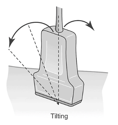
TILTING (FANNING) the Ultrasound Probe
Tilting the ultrasound probe involves moving the transducer from side to side along the short axis of the probe. It is commonly also called “Fanning” as well. Tilting will allow visualization of multiple cross-sectional images of a structure of interest. You can apply this technique to structures such as the heart, kidney, bladder, vessels, etc.
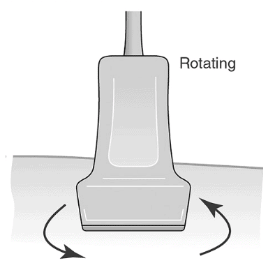
ROTATING the Ultrasound Probe
Rotating the ultrasound probe involves turning the transducer in a clockwise or counterclockwise direction along its central axis. Rotation is most commonly used to switch between the long and short axis of a specific structure such as a vessel, the heart, the kidney, etc.
In the example below, we are going from a short axis to the long axis of the brachial artery by rotating clockwise 90 degrees:
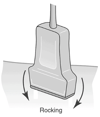
ROCKING the Ultrasound Probe
Rocking the ultrasound probe involves “rocking” the ultrasound probe either towards or away from the probe indicator along the long-axis.
Rocking allows you to help center the area of interest. This is also referred to as “in-plane” motion because the image is kept in-plane throughout the manipulation.
Here is an example of rocking the ultrasound probe:
COMPRESSION with the Ultrasound Probe
Compression with the ultrasound probe involves putting downward pressure on the probe to evaluate the compressibility of a structure or organ of interest. The most common use is to evaluate for deep vein thrombosis, differentiate between artery versus vein, and evaluation for appendicitis (non-compressible).
Here is an example of compression used to compress the brachial artery and vein:
Indicator (Orientation Marker) Position
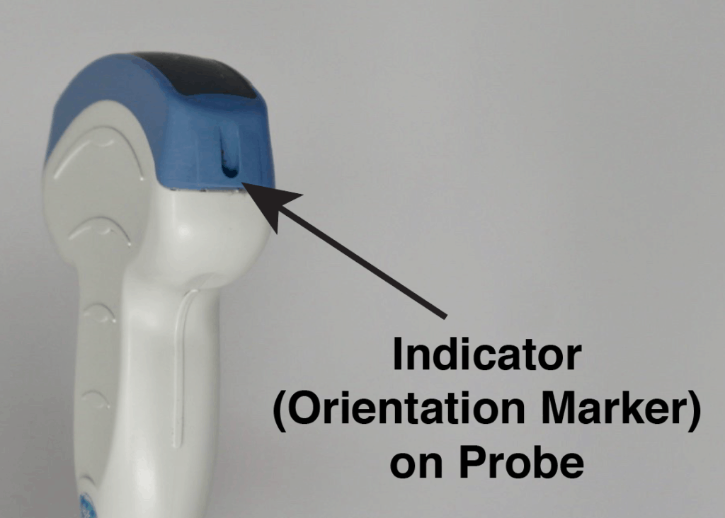
Ultrasound PROBE Indicator (Orientation Marker) Position
The “probe indicator” on the ultrasound probe can be identified as an orientation marker (ridge, indentation, groove, or nub) on one side of the probe. This corresponds to the indicator or orientation marker on the ultrasound image.
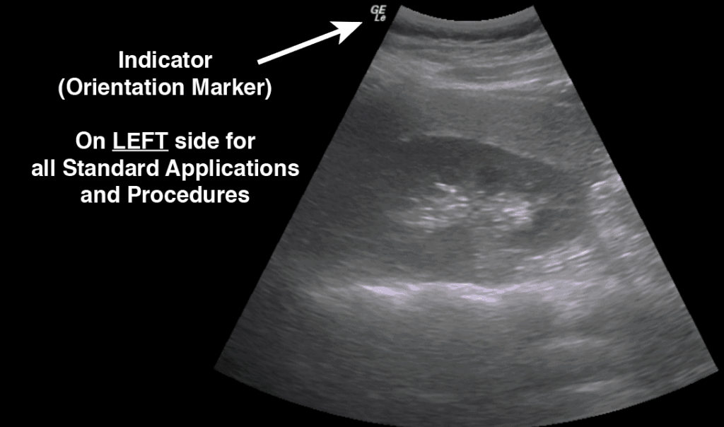
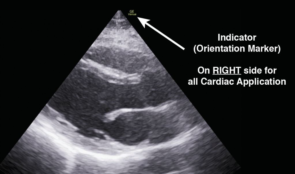
Ultrasound IMAGE Indicator (Orientation Marker) Position
In general, for almost all standard applications and procedures the indicator orientation marker position will be on the LEFT side of the screen. In cardiac mode, the indicator orientation marker will be on the RIGHT side of the screen.
Ultrasound Imaging Planes/Orientation
Radiographically, the body is divided into three distinct planes: Sagittal, Coronal, and Transverse. Any combination of those movements is considered “Oblique.”
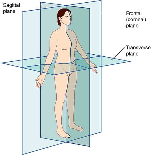
Sagittal Plane
Parallel to the long axis of the body and separates the body from left to right.
Transverse Plane
Perpendicular to the long axis of the body and separates body from top (superior) to bottom (inferior).
Coronal Plane
Parallel to the long axis of the body and separates the body from front (anterior) to back (posterior).
Oblique Plane
Oblique imaging planes refer any plane that uses a combination of those planes.
Short Axis and Long Axis Orientation:
Cylindrical and non-circular structures can additionally be described using the terms Short vs Long axis.
Long Axis: plane parallel to the maximal length of a structure.
Short Axis: plane perpendicular to the long-axis of a structure.
These views can be obtained by rotating 90 degrees relative to each other. These terms are helpful in structures such as vascular and cardiac applications. Also, this is useful when deciding to perform a procedure in a short versus long-axis approach.
Below we are rotating between a short-axis and long-axis of the brachial artery using a clockwise rotation of 90 degrees.
Here is an example of the long axis and short axis of the heart. The parasternal short axis is obtained by rotating 90 degrees clockwise from the parasternal long axis view.
Like this Post?
Sign Up For POCUS 101 Updates!
Ultrasound Knobology and Settings: Step-by-Step Approach
Starting to use an ultrasound machine can feel really intimidating since they seem to have so many knobs and buttons!
The good news is that all ultrasound machines have the same basic settings and once you understand them you can start using any ultrasound device with ease.
I would suggest approaching any ultrasound machine in with the following order using the step-by-step approach below. I’ve found doing it in this order prevents you from forgetting to optimize basic ultrasound settings that can drastically improve your image quality.
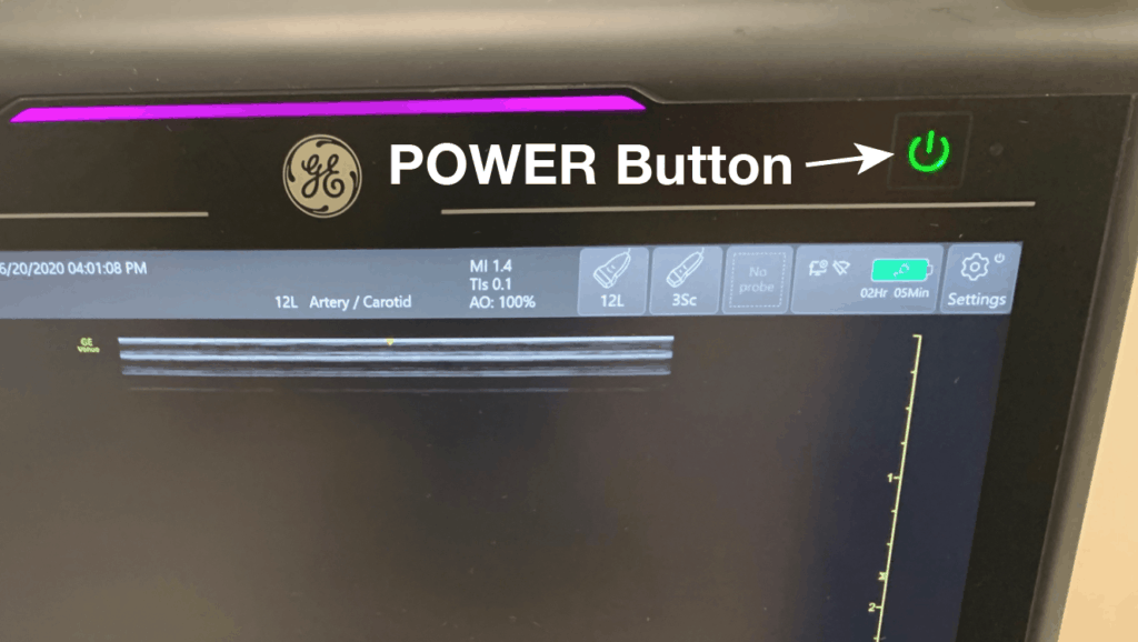
Knobology Step 1: Power Button
Yes the most important button of all is the power button! Simple enough!
This is an interesting fact: the on and off buttons were derived from a binary numbering system where “0” was for OFF and “1” was for ON. So to create the universal symbol for Power the “0” and “1” were combined to make the following symbol:
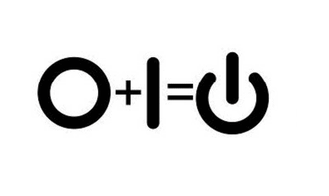
This power symbol applies to almost all ultrasound devices as well. Just look for it when you want to turn on your machine.
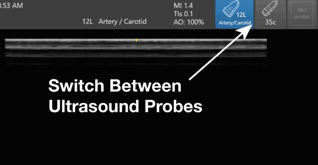
Knobology Step 2: Switch to the Correct Ultrasound Probe/Transducer
If you read the beginning of this post, you should already know what ultrasound probe you need to use based on the application you are performing. So after turning on the ultrasound machine, the next most important step is to switch to the correct ultrasound transducer you will need.
This seems like common sense but I’ve seen many learners just want to jump in and start scanning with the wrong transducer. Unfortunately, understanding all of the ultrasound knobs won’t mean much if you have the wrong ultrasound probe to start off with!
Every machine will have a way to for you to switch between transducers.
(Editor’s note: for the Butterfly. You don’t actually have to switch between transducers because it is an “all-in-one” device. When you switch the application preset it will automatically simulate the correct transducer settings for you)
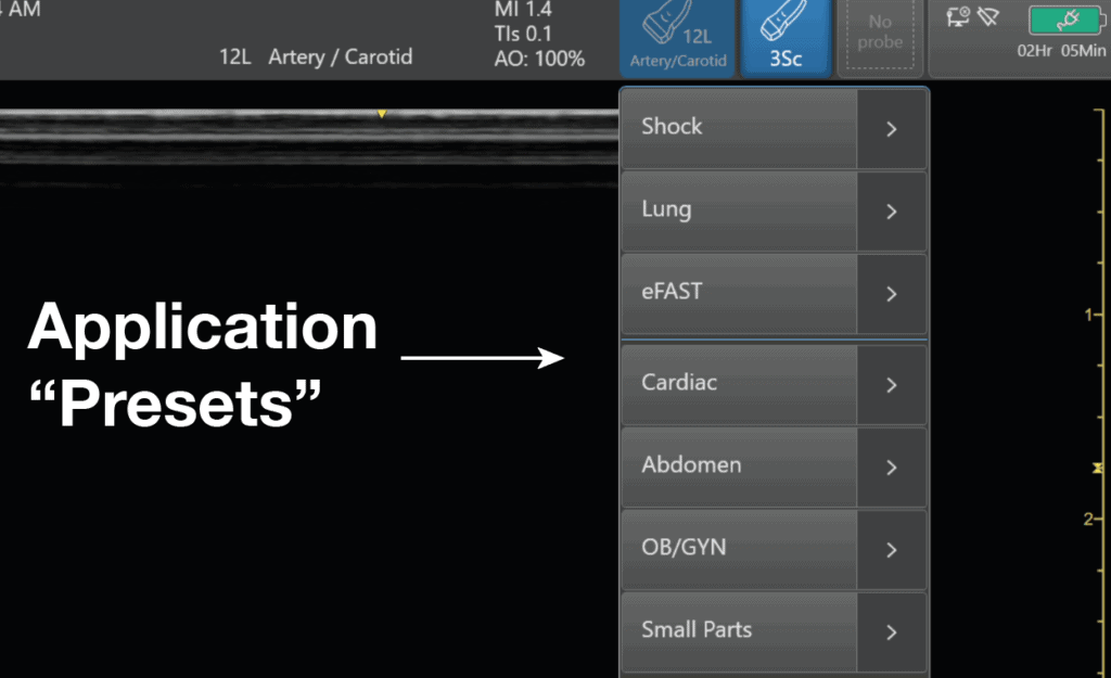
Knobology Step 3: Application Preset
After switching to the correct ultrasound probe, the next step is to select the correct application preset for that transducer.
Each transducer will have a different list of application presets based on its frequency and footprint. The ultrasound device companies will create application presets that make sense for those specific probes.
Think of selecting the ultrasound application preset like how you would select the correct preset for your point and shoot camera. You would use a different setting for day mode versus light mode. The camera will help adjust the settings to optimize for those specific conditions.
Selecting the correct application preset is similar in that it will automatically select the ideal frequency, depth, and gain for that application (i.e. cardiac vs abdominal). This gives you a great starting point to further fine-tune your image with the other knobs/buttons (depth, gain, focus, TGC, etc). In addition, the ultrasound will always start in B-mode or “greyscale” mode by default.
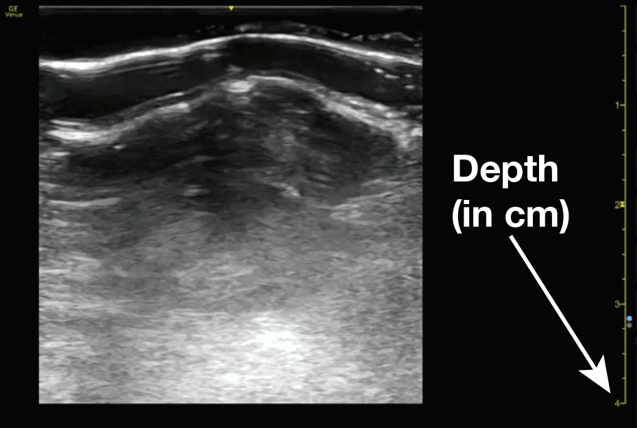
Knobology Step 4: Depth
Now the application preset will usually give you a decent image right when you place the ultrasound probe on the patient. However, there are some ultrasound settings that may need to be adjusted to optimize your ultrasound settings further.
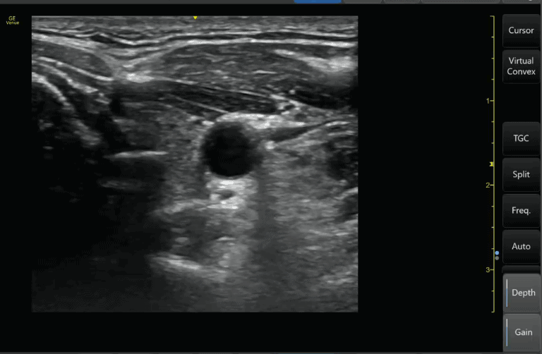
The first of these ultrasound settings you should adjust is the depth. The ultrasound depth setting is simply how deep you want the ultrasound machine to be able to scan.
The rule of thumb is to only use as much depth that is necessary to see your structure of interest. Often times for beginning users, their depth will be too high and there is a lot of wasted “Ultrasound Real Estate” on the bottom of the screen.
The right side of the screen will have dots or lines that correspond to the depth in centimeters. This can give you an estimation of how deep your structures are as well. As you INCREASE the depth setting on your machine, you will see the numbers increase on the right side of the screen to correspond to the depth of penetration.
Here is an example of increasing the ultrasound depth to visualize a deeper structure:
Conversely, if you decrease the depth you will be visualizing more superficial structures. Here is an example below of decreasing depth:
Knobology Step 5: Gain (Overall)
After optimizing your depth, the next ultrasound setting you should adjust is your gain.
Ultrasound gain simply means how bright or dark you want your image to appear. It increases or decreases the strength of the returning ultrasound signals that you visualize on the screen.
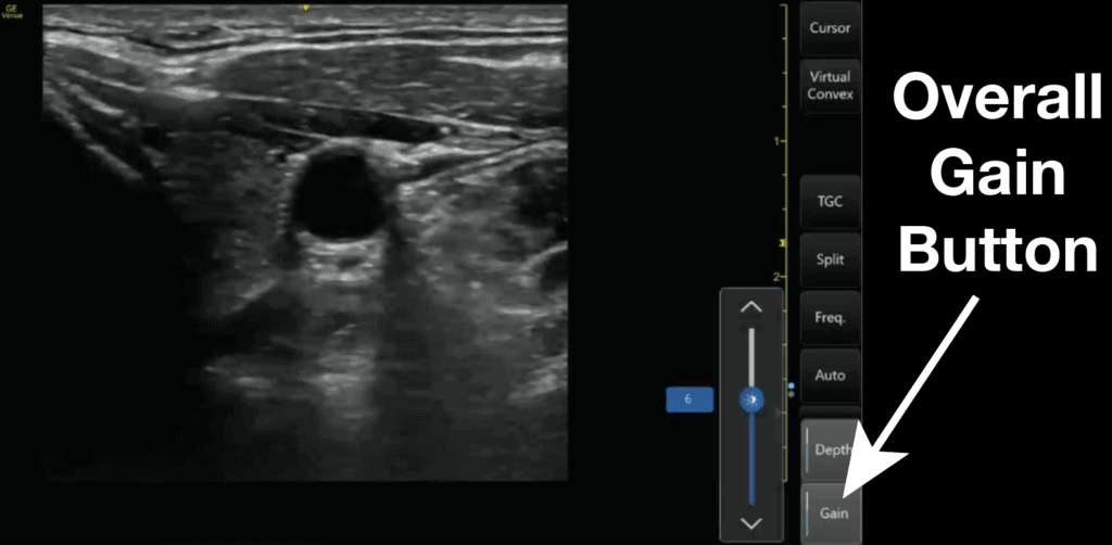
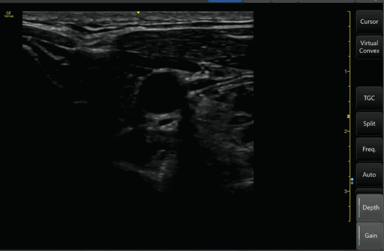
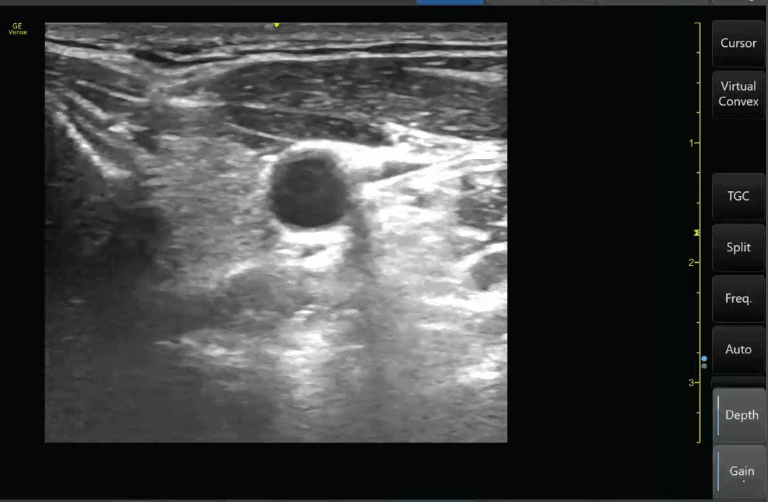
All ultrasound machines will have an “Overall” Gain setting that, when increased or decreased, will make the entire ultrasound image brighter or darker. This is good to use when your entire imaged is too dark (under-gained) or too bright (over-gained).
(Editor’s note: Regarding this section, we are referring to Gain in the setting of B-mode/greyscale. You can also change the gain in your Doppler modes which we will discuss in the following section on “Advanced Modes.” Lastly, some machines have an “Autogain” button that I rarely use because I find it typically undergains your image.)
Knobology Step 6: Near/Far Field Gain and Time Gain Compensation (TGC)
Most ultrasound machines will have settings that allow you to fine-tune and adjust the gain at specific depths of your greyscale ultrasound image. These will be termed Near/Far field gain or Time Gain Compensation (TGC).
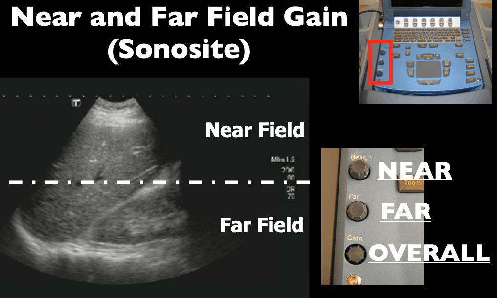
Near Field and Far Field Gain (Sonosite)
The commonly used Sonosite M-Turbo or Edge machines allow you to adjust the “Near field” and “Far field” gain of your ultrasound images. The near field refers to the top half of the ultrasound screen and the far field refers to the bottom half of the ultrasound screen. The overall gain is just called “Gain” and is on the bottom left-hand corner of the Sonosite machine buttons.
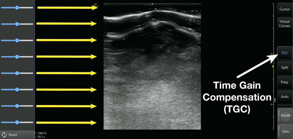
Time Gain Compensation (TGC)
Most other ultrasound machines will allow you to further adjust the gain in even more specific areas of your ultrasound screen. This ultrasound setting is called “Time Gain Compensation” or TGC.
Adjusting the Time Gain Compensation (TGC) allows you to adjust the gain at almost any depth of your ultrasound image, not just the near and far-fields. The top rows of the Time Gain Compensation control the nearfield gain and the bottom rows control the far-field gain.
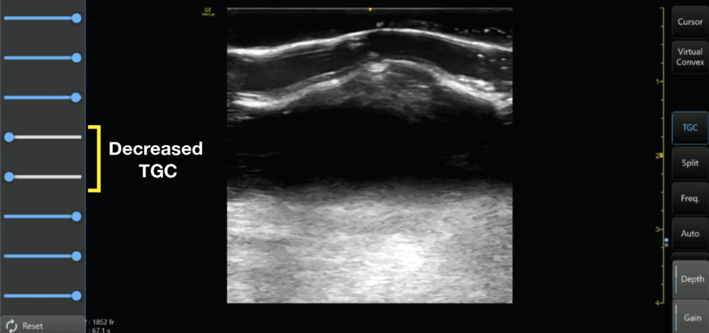
Here is an example of decreasing the TGC of the middle of the image with a corresponding absence of echoes on the middle of the ultrasound screen.
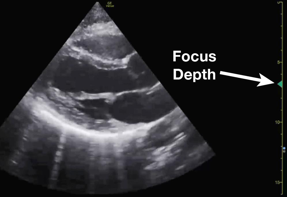
Knobology Step 7: Focus
The last ultrasound setting you can use to optimize your image is by adjusting the focus. When you adjust your focus you are simply concentrating your ultrasound waves at a specific depth of the image to maximize the resolution at that depth.
Some machines like the Sonosite don’t allow adjusting the focus since the machine has auto-focus built in.
However, if a machine does allow you to adjust the focus, it is very important to place the focus cursor to the depth of the area of interest. Usually, the focus is indicated by a small arrow (or hourglass) superimposed on the depth markings.
Knobology Step 8: Freeze, Measure (Caliper), Image/Video Capture
If you went through the previous steps then you should have a really good and optimized image. Here are just some other buttons you may encounter that may be useful if you need to freeze, measure, or capture your ultrasound image.
Freeze
Just like the world implies, the “freeze” button freezes a frame for you so you have time to view it in more detail. The ultrasound machine will usually store a 10-30 seconds of data and you can scroll back to see previous frames as well.
Calipers (measure)
Calipers are an important feature of ultrasound machines that allows you to measure the distance of specific structures of interest.
Image/Video Capture
All ultrasound machines will allow you to save an image and/or video clip of your ultrasound scan. This is important if you are trying to archive, bill, or use any ultrasound images/videos as teaching files.
Video example of Freeze, Measure, Image Capture:
Below is a quick video demonstrating how to use all of these functions (freeze, measure, image capture) by measuring the LVOT (left ventricular outflow tract) diameter. You can use this same technique to measure any other structure of interest.
Like this Post?
Sign Up For POCUS 101 Updates!

Basic Ultrasound Modes (B-Mode and M-Mode)
Now it may seem daunting when thinking about all of the available ultrasound modes available. In this section, the most common and basic ultrasound modes: B-mode and M-mode. In the following section, I will cover the more advanced Doppler Modes.
I would suggest that if you are just starting out, focus on B-mode (greyscale), and get really good at obtaining high-quality 2D images. After you feel comfortable with B-mode start adding on and learning the other more advanced Doppler modes. You can always come back to this post as a reference when you are ready to use the other modes!
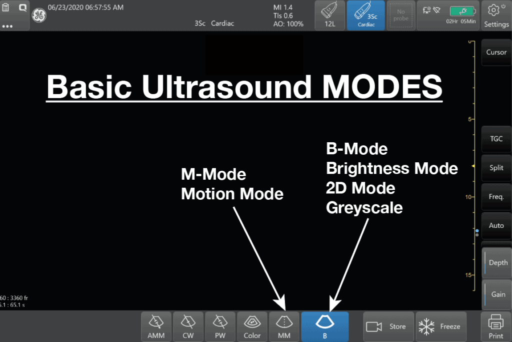
B-Mode (Brightness Mode) or 2D mode
B-Mode (Brightness Mode) in ultrasound is a setting that creates a two-dimensional (2D) greyscale image on your ultrasound screen and is the most commonly used mode. It is also commonly called 2D mode.
B-mode is the single most important mode you need to master in order to be proficient at point of care ultrasound (POCUS). All of the other modes rely on you getting a good B-mode (2D) image. Fortunately, we already discussed the most common ultrasound settings for B-mode in the ultrasound Knobology section above.
The buttons to get you back to B-mode/2D can be:
- B (just the letter) – GE machines
- 2D (Sonosite and Philips)
POCUS 101 Tip: Sometimes, you may be in a different mode or ultrasound machine setting and may wonder how to just reset your settings. Usually pushing the B-mode or 2D button on the ultrasound machine will reset everything and bring you back to the simple B-mode setting.
M-Mode (Motion Mode)
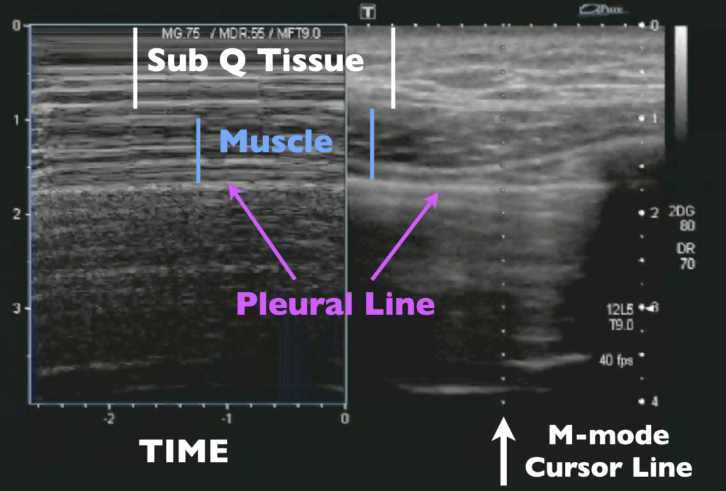
Ultrasound M-mode is defined as a motion versus time display of the B-mode ultrasound image along a chosen line. The motion is represented by the Y-axis and time is represented by the X-axis. Common applications for M-mode include looking at E point septal separation in cardiac scanning or calculating fetal heart rate for obstetrics. You can also use M-mode in lung ultrasound to evaluate for lung sliding and rule out pneumothorax.
Below is an example of how the M-mode (left side of screen) and B-mode (right side of screen) compare when looking at lung sliding. M-mode simply takes a “slice” of your B-mode image where the cursor line is placed and translates that “slice” over time. It ignores everything else on the B-mode scan except for where you have that cursor line. You can see on the Y-axis how the structures (subcutaneous tissue, muscle, and pleural line) correlate between the M-mode and B-mode images. You can also see the relative motion of these structures over time (X-axis).
Here are the steps to acquiring an M-mode Image:
- M-mode Step 1: Acquire 2D image and Center Structure of Image
- M-mode Step 2: Push the M-mode button to make the M-mode cursor line appear
- M-mode Step 3: Place the M-mode cursor line along the structure of interest
- M-mode Step 4: Push the M-mode button again to activate M-mode
- M-mode Step 5: Push the Freeze Button
- M-mode Step 6: Scroll to the desired image
- M-mode Step 7: Push the Measure Button
- M-mode Step 8: Measure Area of Interest
Here is also a video of performing the 8 steps of M-mode to measure Cardiac E-point Septal Separation (EPSS):
Here is another example of how to use M-mode to look for lung sliding and pneumothorax on ultrasound:
Advanced Ultrasound Modes (Doppler)
Besides B-mode and M-mode you will have other advanced ultrasound Modes that involve “Doppler.” Here is an image of all the available ultrasound modes:
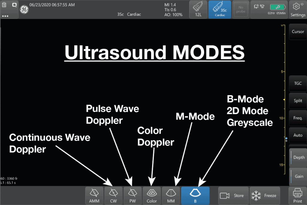
Initially, these Doppler modes may seem confusing but in reality, all Doppler settings are simply meant to detect speed going either Towards or Away from your probe (check out our previous post on Doppler Physics HERE). Understanding this is the first step to mastering ultrasound Doppler.
Doppler Shift Equation
All Doppler signals (regardless of which Doppler mode you are using) are calculated using the Doppler Shift Equation. Below is a figure detailing how the Doppler Shift is used and how the angle of insonation is extremely important in what the transducer will detect as the speed of flow/movement. For any type of Doppler, you want the flow/movement to be going directly towards your probe (zero degrees). As you move more towards a 90-degree angle there will be no flow detected by the ultrasound machine.
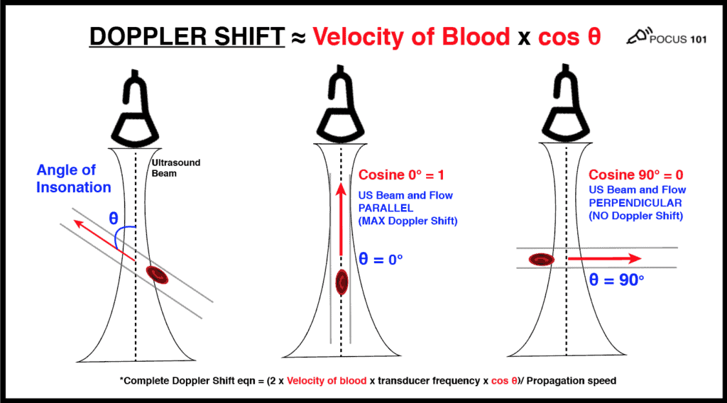
(Editor’s note: I’m using the velocity of blood as the example here. But the same principles apply if you are measuring muscle movement using tissue doppler.
So the most important thing you can do to improve your technique for any Doppler mode is to make sure that the movement/speed of whatever you are measuring is parallel to your ultrasound probe as much as possible (zero degrees). Anything above 25-30 degrees will significantly underestimate your measurements. And if you are perpendicular, the cosine of 90 degrees = 0 and the ultrasound Doppler will read no flow or movement.
Color Doppler Mode
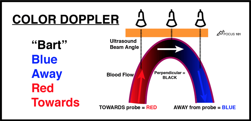
The most common Doppler mode you will use is color Doppler. This mode allows you to see the movement of blood in arteries and veins with blue and red patterns on the ultrasound screen.
A common question that comes up with color Doppler is: What do the colors on ultrasound mean? The answer is: RED means there is flow TOWARDS the ultrasound probe and BLUE means that there is flow AWAY from the ultrasound probe. It is a misconception that red is arterial and blue is venous. It actually just depends on the direction blood is flowing relative to the angle of your ultrasound beam.
An easy way to remember this is to use the BART mnemonic: Blue AWAY, Red TOWARDS.
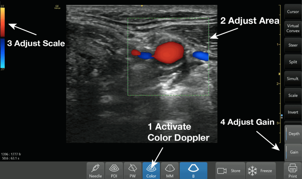
Color Doppler Steps:
- Color Doppler Step 1: Activate Color Doppler
- Color Doppler Step 2: Adjust Color Doppler Area
- Color Doppler Step 3: Adjust Color Doppler Scale
- Color Doppler Step 4:Adjust Color Doppler Gain
Here is a video demonstrating all of these steps for Color Doppler:
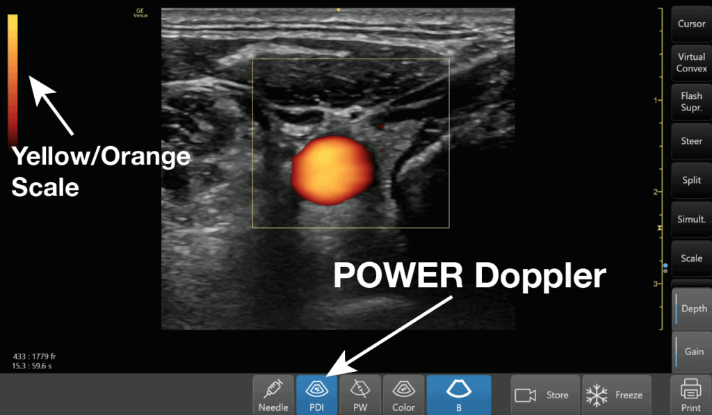
Power Doppler Mode
There is a mode similar to color Doppler that you may encounter called Power Doppler. This mode does not show up as red or blue on the screen but only uses a single yellow color signifying the amplitude of flow. So you can’t tell if the flow is going towards or away from the probe given that it has only one color. It is more sensitive than color Doppler and is used to detect low flow states such as venous flow in the thyroid or testicles.
Like this Post?
Sign Up For POCUS 101 Updates!
The “Other” Doppler Modes
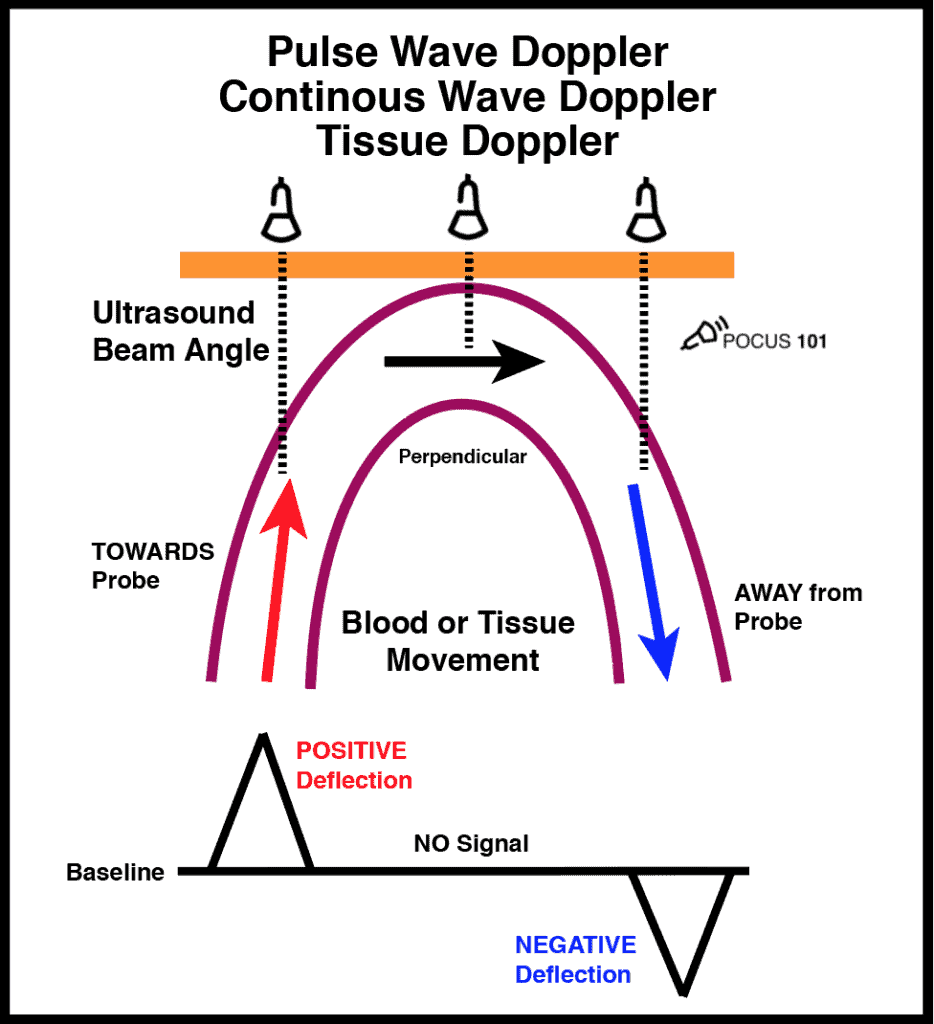
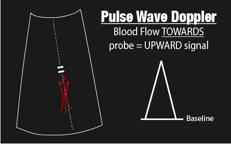
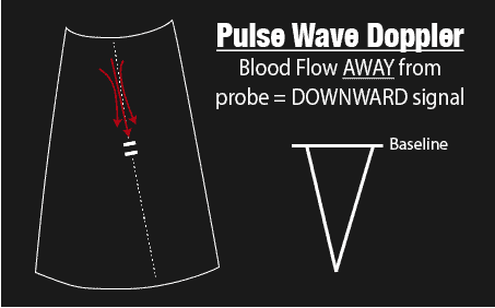
Now some learners may feel like the “other doppler modes” such as Pulse wave, Continuous wave, and Tissue Doppler are very advanced settings. However, the same principles of color Doppler apply to these other Doppler modes as well. The ultrasound probe is just detecting flow or motion either TOWARDS or AWAY from it. If flow/motion is towards the probe there will be a positive deflection and if it is away from the probe there will be a negative deflection.
Here is an illustration that sums up the those Doppler modes:
Pulse Wave (PW) Doppler Mode
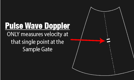
Pulse Wave (PW) Doppler allows you to measure the velocity of blood flow (at a single point). A unique aspect of Pulse Wave Doppler is that you can specify to the ultrasound machine exactly where you would like the machine to measure the velocity using the Sample Gate. It’s usually seen by two horizontal lines along your cursor. you can move your cursor and your sample gate and place it exactly where you want to measure your blood velocity.
See the example figures below:
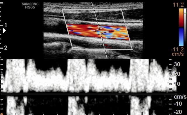
The biggest limitation with Pulse Wave Doppler, however, is that there is a limit on the maximum speed you can detect. Anything past this limit (termed Nyquist Limit) will cause the signal to alias. In general, you do not want to use Pulse Wave Doppler for any applications that require measuring speed above 200cm/second.
This is why you can’t use this mode for very high-velocity applications such as severe regurgitation or stenosis of the heart valves. Here is an example of aliasing with pulse wave Doppler:
Common applications of pulse wave Dopplers are to measure cardiac output (LVOT VTI) or diastolic dysfunction.
Here are the steps to properly use Pulse Wave Doppler after you acquire your 2D image:
- PW Doppler Step 1: Push Pulse Wave Doppler Button to make PW Cursor line appear
- PW Doppler Step 2: Place PW Sample Gate at Area of Interest
- PW Doppler Step 3: Push PW button again to activate Pulse Wave Doppler Mode
- PW Doppler Step 4: Adjust the PW Gain, Baseline, and Scale
- PW Doppler Step 7: Adjust the Sweep Speed (how many seconds are shown on the X-axis, see video below for example)
- PW Doppler Step 8: Push the Freeze Button
- PW Doppler Step 9: Scroll to the desired image
- PW Doppler Step 10: Push Measure Button
- PW Doppler Step 11: Measure Area of Interest
Here is a video demonstrating all of these Pulse Wave Doppler steps to calculate the Velocity Time Integral of the left ventricular outflow tract:
Also here is a video on how to use pulse wave doppler to measure diastolic dysfunction:
Continuous Wave (CW) Doppler Mode
Continuous Wave Doppler is very similar to pulse wave Doppler except it does not alias and can detect very high velocities (greater than 1000cm/second). So Continuous Wave Doppler is the optimal choice for measuring high-velocity applications such as valvular stenosis and regurgitation.
Unlike Pulse Wave Doppler which has a sampling gate to measure a single point along your cursor, Continuous Wave Doppler measures all points along your cursor. Therefore what you will see will be the maximum velocity of flow detected along the cursor line. This is a pro and a con. It is a pro because you don’t have aliasing and can detect high velocities, but it is a con because you don’t know exactly where that velocity is coming from on the cursor. Also if there are two velocities along the cursor line, you won’t be able to differentiate the lower velocity compared to the higher velocity signal, since the high-velocity signal will mask the low-velocity one.
The steps to performing continuous wave Doppler are the similar to Pulse wave Doppler except where you put the sample gate does not matter. It will measure velocities across the entire cursor line.
Steps to performing Continuous Wave Doppler:
- CW Doppler Step 1: Push Continuous Wave Doppler Button to make CW Cursor line appear
- CW Doppler Step 2: Place CW Cursor at Area of Interest (where you put the sample gate doesn’t matter)
- CW Doppler Step 3: Push CW button again to activate Continuous Wave Doppler Mode
- CW Doppler Step 4: Adjust the CW Gain, Baseline, and Scale
- CW Doppler Step 7: Adjust the Sweep Speed (if needed)
- CW Doppler Step 8: Push the Freeze Button
- CW Doppler Step 9: Scroll to the desired image
- CW Doppler Step 10: Push Measure Button
- CW Doppler Step 11: Measure Area of Interest
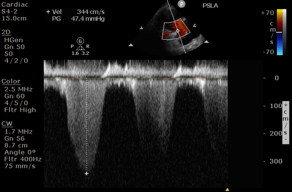
Here is an example of measuring tricuspid regurgitation (TR) using continuous wave Doppler. Notice how CW Doppler can measure the high velocity of this TR jet (344cm/s).
Tissue Doppler Imaging (TDI) Mode
Now let’s go over how to use Tissue Doppler.
The good news is that all of the principles of Pulse Wave Doppler also apply to Tissue Doppler. In fact, Tissue Doppler is just another form of Pulse Wave Doppler that allows you to measure the much slower speeds of tissue/muscle movement (from 1cm/s – 20cm/s) compared to Pulse Wave Doppler that measures the much faster speed of blood (30cm/s – 200cm/s).
Accessing the Tissue Doppler function will vary by machine but usually just involves pushing a knob/button labeled “TDI” (Tissue Doppler Imaging) while you are in the Pulse Wave Doppler mode.
Here are the steps to using Tissue Doppler Imaging:
- TDI Doppler Step 1: Push Pulse Wave Doppler Button
- TDI Doppler Step 2: Place Sample Gate at Area of Interest
- TDI Doppler Step 3: Push TDI button to activate TDI Mode
- TDI Doppler Step 4: Adjust the TDI Gain, Baseline, and Scale
- TDI Doppler Step 5: Adjust the TDI Scale (if needed)
- TDI Doppler Step 6: Adjust the Sweep Speed
- TDI Doppler Step 7: Push the Freeze Button
- TDI Doppler Step 8: Scroll to the Desired Image
- TDI Doppler Step 9: Push Measure Button
- TDI Doppler Step 10: Measure Area of Interest
Here is a Step-by-Step video on how to use Tissue Doppler by measuring the medial e’ to evaluate diastolic function:
Other Ultrasound Doppler Settings: Wall Filter, Steer, Angle Correction
When you are in one of these Doppler settings, you will be able to optimize your image further by adjusting the following ultrasound buttons/knobs:
- Wall Filter: decreases low-velocity signals. Used to minimize the amount of artifacts on your Doppler images
- Steer: allows you to steer the color Doppler box when you can’t get an optimal angle
- Angle Correction: used for Pulse wave to correct the angle of your sample gate when you can’t get an optimal angle
This video explains how to use all three of these ultrasound settings:
Ultrasound Knobology Summary
I hope you found this post helpful! Here is a Video summarizing the most commonly used ultrasound knobs, probes, and modes:
References
- AIUM technical bulletin. Transducer manipulation. American Institute of Ultrasound in Medicine. Journal of ultrasound in medicine : official journal of the American Institute of Ultrasound in Medicine 1999
- Bahner, D., Blickendorf, J., Bockbrader, M., Adkins, E., Vira, A., Boulger, C., Panchal, A. (2016). Language of Transducer Manipulation Journal of Ultrasound in Medicine 35(1), 183 – 188. https://dx.doi.org/10.7863/ultra.15.02036
- Ransingh. Teaching Point-of-Care Ultrasound (POCUS) to the Perioperative Physician. 2018. https://doi.org/10.1017/9781316822548.013
- Case courtesy of Dr Balint Botz , Radiopaedia.org. From the case rID: 64786


This has been tremendously helpful! Thank you very kindly for this summary.
From a POCUS novice
Absolutely! Anytime. glad you found it helpful!
It’s a great tutorial. Thank you
Thanks so much! Glad you found it helpful 🙂
Thanks Vi for this great tutorial!
Inspiring to see & learn from. : )
Hi Asaf. Thanks so much for the kind words!! Good luck on your POCUS journey and glad we can be a part of it.
Awesome descriptions! Thank you!
Thank you so much Jules!
Great summary , very helpful . Thank you
Awesome! So glad you found it helpful.
Fantastic! Simple & devoid of technical terms.
Thanks so much Hameed!
[…] knobs/buttons (depth, gain, focus, TGC, etc). In addition, the ultrasound will always start in B-mode or “greyscale” mode by […]
[…] get the Aortic Valve level from the Mitral Valve level, tilt the tail of the probe inferiorly and point it towards the Aortic […]
I gained a lot
That is great! Appreciate the comment and kind words.
Thanks a lot
Wonderful description.It clears my doubts about this topic.
Awesome Ali! Good luck on your POCUS Journey.
[…] Para obtener cada punto de referencia en las vistas discutidas a continuación, la sonda de ultrasonido a menudo necesitan ser manipulados en un número de orientaciones. […]
Excellent post!
Thanks Danielle!!
what year wad this website published
I chole. Our first post was early 2020! Thanks
Thank You very Much for this Extra-ordinary work
Thanks Moustafa for the kind words!
This is really great ,it has cleared my basic concepts and lessen the confusion of handling the machine which nobody teaches this way. Kindly guide how can I connect with you for further guidance regarding ECHO.
Kind Regards.
Hi Dr. Shaista Jabeen. Yes you can find more echo posts on our blog or on our courses: https://courses.pocus101.com/
very helpful just testing for mice aorta aneurysms growth
Thank you Steve! Best of luck with the Mice work
[…] Further reading: 1. Enriquez JL and Wu TS. An introduction to ultrasound equipment and knobology. Crit Care Clin. 2014 Jan;30(1):25-45, v. doi: 10.1016/j.ccc.2013.08.006. 2. Wiafe YA and Badu-Peprah. The Influence of Ultrasound Equipment Knobology in Abdominal Sonography. In: Essentials of Abdominal Ultrasound, Gamie SAA and Foda EM (ed.) [online] 2019. DOI: 10.5772/intechopen.83713 3. Dinh V. Ultrasound Machine Basics-Knobology, Probes, and Modes. Pocus 101 [online] https://www.pocus101.com/ultrasound-machine-basics-knobology-probes-and-modes/#B-Mode_Brightness_Mod… […]